A beam looks like a simple horizontal member at a construction site. However, a lot happens inside it when the workers place a load on top. The beam has one basic job: take the load and transfer it safely to its supports. The simply supported beam is one of the best examples of how it works. Suppose a plank that rests on two supports. The plank will bend slightly if you place a load in the middle. The same principle applies to a structural beam. But remember that a simply supported beam in construction involves many other factors. Some of these factors include the following:
- Proper calculations
- Material properties
- Reinforcement
- Safety requirements
Read on this blog post to understand the simply supported beam diagram with real-world examples and its deflection formula.
Quick Answer
A simply supported beam is a beam that rests on two supports. It allows rotation at the supports while resisting vertical movement. Thus, the beam bends and develops deflection under load.
The maximum deflection for a central point load is:
δmax = PL³ / 48EI
The maximum deflection for a uniformly distributed load is:
δmax = 5wL⁴ / 384EI
The engineers use these standard elastic beam relations to understand beam behavior. The common real-world examples are as follows:
- Park benches
- Precast concrete slabs
- Window and door lintels
- Single-span bridge decks
- Wooden plank over a ditch
- Roof rafters
What Is a Simply Supported Beam?
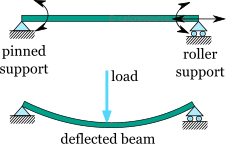
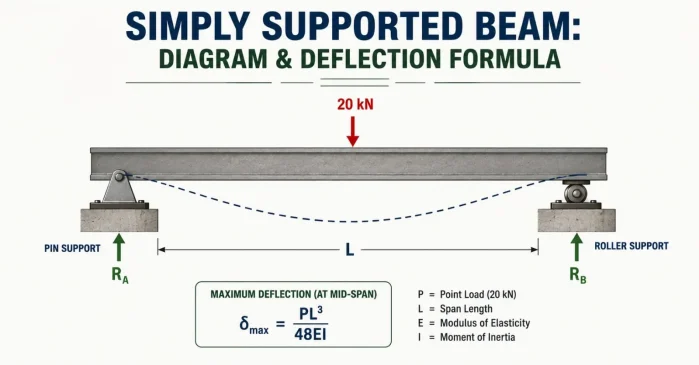
A simply supported beam is a horizontal structural element. It rests on two supports at its ends. One side has a pin (hinge), and the other side has a roller. The result? It not only rotates freely but also bears vertical loads efficiently. Most importantly, it avoids buildup of internal thermal stress as it is flexible.
Given below are the key characteristics of a simply supported beam:
- Pin Support: It holds the beam horizontally and vertically. Moreover, it allows the beam to rotate properly.
- Roller Support: This element supports the vertical weight. The beam slides back and forth easily to adjust for temperature changes.
- Zero End Moments: The supports don’t hold back a turning force. This is why the bending moment at both outer edges is zero.
- Statically Determinate: Engineers use the basic balance rules to find all support reactions.
What Does a Simply Supported Beam Look Like?
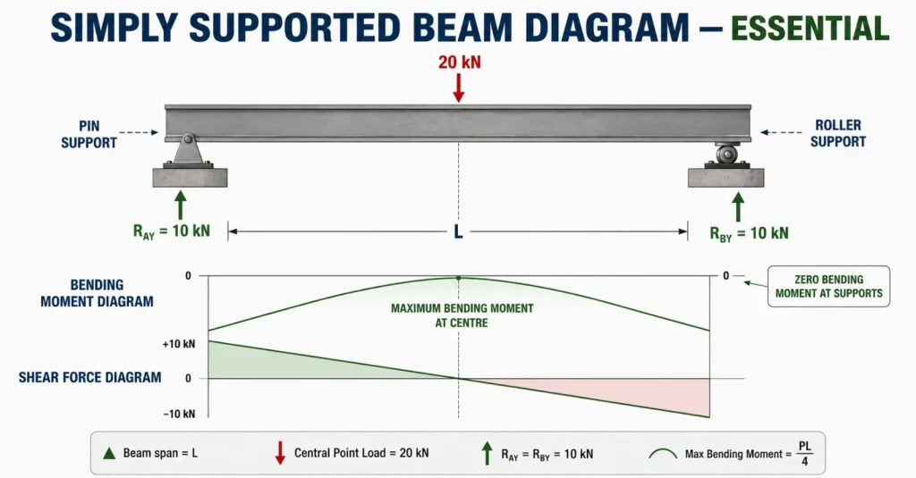
Given below are the components of a simply supported beam diagram:
- The Beam Span (L)
It is the total horizontal distance between the two supports. The diagram highlights that the beam stretches from the left pin support to the right roller support. The span L is important because it directly affects the bending and deflection of the beam.
- Pin/Hinged Support (Left)
The left end rests on a pin or hinged support. It allows the beam to rotate easily. This support develops two reaction components known as a horizontal reaction (Rₐₓ) and a vertical reaction (Rₐᵧ). The horizontal reaction is zero in the above diagram. This is because there is no horizontal load.
- Roller Support (Right)
The right end rests on a roller support. It prevents vertical movement but ensures seamless horizontal movement. This is useful because a beam may need to expand or contract due to temperature changes. The reaction in this example is 10 kN.
- 20kN Point Load
The downward arrow at the centre represents a 20 kN concentrated load. This load is shared between the two supports. This is because the load positions are at the centre and the beam is symmetrically supported.
- Support reactions
The two upward arrows represent the reactions developed by the supports. Thus, each support carries 10 kN. This provides the total upward reaction of 20 kN.
- Shear Force Diagram (SFD)
The lower graph highlights the changes in internal shear force with a simply supported beam. The shear force is +10 kN from the left support. It drops by 20 kN to -10 kN once it reaches the 20 kN point load.
- Bending Moment Diagram (BMD)
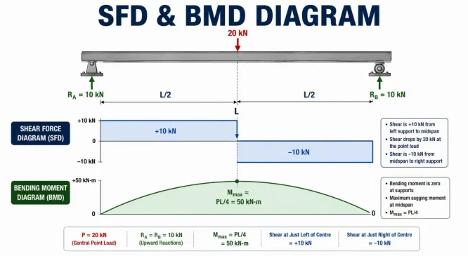
This diagram shows how the bending effect changes along the beam. The bending moment is zero at both supports and reaches its maximum value at the centre for this symmetrical loading arrangement. The beam experiences the greatest sagging effect at this point.
What Is Simply Supported Beam Deflection?
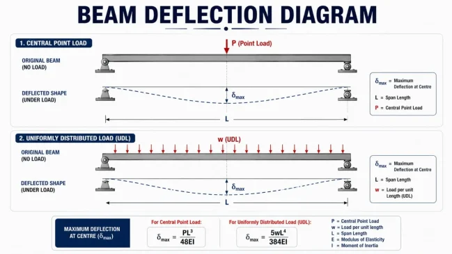
A simply supported beam deflection is the amount by which the beam moves away from its original straight position. The deflection often happens when a load acts on it. Many people confuse a little deflection with a failure of the beam. But in reality, all beams deform to some degree under load.
What Is the Simply Supported Beam Deflection Formula?
The simply supported beam deflection formula depends on the load. The maximum deflection for a central point load P beam is δmax = PL³ / 48EI.
Here each component refers to the following:
- δmax = maximum deflection
- P = central point load
- L = beam span
- E = Young’s modulus of the material
- I = second moment of area
However, the maximum deflection relationship for a beam carrying a uniformly distributed load w is δmax = 5wL⁴ / 384EI.
Here, w is the load per unit length. The term EI represents the beam’s flexural rigidity.
A higher value of E means a stiffer material. A larger value of I means the beam’s cross-section is more resistant to bending.
This is why the dimensions and shape also influence how much the beam bends.
What Are the Real-World Examples of a Simply Supported Beam?
Given below are the real-world applications of a simply supported beam:
- Wooden plank over a ditch
- Single-span bridge decks
- Window and door lintels
- Roof rafters and ceiling joists
- Park benches
- Precast concrete slabs
The Final Words
A simply supported beam is one of the most important concepts in structural engineering. Loads have to travel somewhere. Thus, supports react to those loads. The beam deforms as it carries them. It is advisable to hire an expert engineer who understands each component of the simply supported beam diagram.
FAQs
1. Where Does Maximum Deflection Occur in a Simply Supported Beam?
In a simply supported beam with a point load placed at the center, the beam bends downward most at the midpoint of the span. The symmetrical loading makes the center the critical location for deflection. If the load is placed elsewhere, the maximum deflection will occur at a different point.
2. What Is the Simply Supported Beam Deflection Formula for a Central Point Load?
The standard simply supported beam deflection formula for a central point load is δmax = PL³ / 48EI. Here, P is the applied load, L is the span, E is Young’s modulus, and I is the second moment of area of the beam section.
3. What Is the Deflection Formula for a Uniformly Distributed Load?
When a Simply Supported Beam carries a uniformly distributed load across its entire span, its maximum deflection can be calculated as δmax = 5wL⁴ / 384EI. Here, w is the distributed load per unit length, while L, E, and I represent span, material stiffness and section geometry.
4. Why Does Beam Span Matter So Much?
The span has a strong influence on Simply Supported Beam deflection. For a central point load, deflection depends on L³. For a uniformly distributed load, it depends on L⁴. So, as the beam becomes longer, deflection can increase rapidly unless its stiffness or cross-section is also increased.
5. Does a Simply Supported Beam Have Bending Moment at Its Supports?
Ideally, a Simply Supported Beam has zero bending moment at its supports. The pin and roller supports allow the beam to rotate rather than restraining its ends like fixed supports. As a result, the bending moment develops between the supports and reaches its maximum at an internal section.
6. Why Is Deflection Important in Building Construction?
Simple supported beam deflection is important because too much movement can affect floors, walls, ceilings, finishes, and the overall serviceability of a structure. A beam can be strong enough to carry its load but still deflect excessively. That is why structural design considers both strength and acceptable deflection.